
How to Read an Arduino Nano 33 IOT IMU (8 Steps)
This article covers how to read the IMU (Inertial Measurement Unit) of an Arduino Nano 33 IOT microcontroller.
Step 1. Gather the parts
Below is a list of parts to use with this article:
| Parts (Amazon) |
|---|
| Arduino Nano 33 IoT with headers Mounted |
| AmazonBasics Double Braided Nylon USB 2.0 A to Micro B Charger Cable - 3 Feet, Red |
| LampVPath [12Packs] 170 Points Mini Small solderless breadboard for Arduino Proto Shield (6 Colors) |
Step 2. Create a new sketch
For working with the Arduino Nano 33 IOT I've found it easer to use the Web editor.
Open up the editor at:
If you've never worked with the Web IDE before you will need to signup. You will be prompted when you select an Arduino board to install a plugin. That is so the IDE can upload to and monitor the board.
Create a new sketch.
Step 3. Include the IMU header
Add this above the setup function in the new sketch:
#include <Arduino_LSM6DS3.h>
This includes the library for the 33's built in LSM6DS3 IMU chip.
Another way to include it using the Arduino Web IDE would be to do this:
- Click on the Library Manager icon in the toolbar (usually on the left of the browser window)
- Search for LSM6DS3
- Click the INCLUDE button
- It will then insert the #include statement for you
Step 4. Update the setup function
Replace the setup function with this code:
void setup() {
  Serial.begin(9600);
  while (!Serial) {
    ; // wait for serial port to connect. Needed for native USB port only
  }
  if (!IMU.begin()) {
    Serial.println("Failed to initialize IMU!");
    while (true); // halt program
  }
  Serial.println("IMU initialized!");
}
The code does the following:
- The Serial.begin call sets up the serial monitor for printing debug messages to its console window
- The code will not proceed until the Serial port is ready (otherwise initialize debug messages will be lost)
- Remember to take this while block out if you run the board independent of the USB or it will never proceed
- The IMU.begin call tests to see if the IMU is available
- If the IMU is not available: a message is printed to the serial monitor, then an infinite loop is created to halt the flow of the program
- If all is well a confirmation message is printed to the serial monitor
There is no way to exit an Arduino program on failure. It's not like a program that can exit to an operating system command prompt. The infinite while loop is an alternate way to pause the program.
Step 5. Add local variables to the top of the loop function
Add this code to define local variables to the top of the loop function:
float aX, aY, aZ;
float gX, gY, gZ;
const char * spacer = ", ";
The code above does the following:
- The first line of floats (aX, aY, aZ) are to hold the acceleration values from the IMU
- The second line of floats (gX, gY, gZ) are to hold the gryoscope values from the IMU
- The spacer is a string constant used to separate values in the printed debug statements
Step 6. Add code to read the IMU data into variables
Add the code below to the end of the loop function (just above the functions closing bracket (})):
if (
  IMU.accelerationAvailable()
  && IMU.gyroscopeAvailable()
) {
  IMU.readAcceleration(aX, aY, aZ);
  IMU.readGyroscope(gX, gY, gZ);
  Serial.print(aX); Serial.print(spacer);
  Serial.print(aY); Serial.print(spacer);
  Serial.print(aZ); Serial.print(spacer);
  Serial.print(gX); Serial.print(spacer);
  Serial.print(gY); Serial.print(spacer);
  Serial.println(gZ);
}
- The if statement tests to see if the acceleration and gyroscope data are available to read
- The IMU readAcceleration call sets the aX, aY and aZ variables with the current acceleration data along each axis
- The IMU readGyroscope call sets the gX, gY and gZ variables with the current gyroscope data long each axis
The remaining code prints a line of the data to the serial monitor.
Why not use sprintf?
You may be wondering why I didn't use sprintf to simplify the print statements. It turns out that the Arduino version of sprintf doesn't support floating point numbers. So a format string like %f returns a blank value. There are creative ways to get around that. But it makes the code more complicated than it needs to be.
Step 7. Load the sketch on to the board
To load the sketch on to the board, do the following:
- Plug your Arduino Nano 33 IOT into your Mac or PC using a USB cable
- At the top of the editor search for the board (Arduino Nano 33 IOT)
- If you see more than one, pick the first one (if for some reason it doesn't work, try another one)
- Click the Upload and Save (right pointing arrow (→)) button to upload the file to the board and save you current work
- Check the window below the code to make sure everything is green and successful
- If the text turns red, see if you can spot the error
If you still have issues, see the Troubleshooting section later in this article.
Also see the complete listing below and compare to what you wrote.
Step 8. Test the IMU
To test the IMU do the following:
- In the Arduino Web IDE click the Monitor button in the tool bar
- Don't worry if you see a message containing port unavailable - it takes a moment to connect
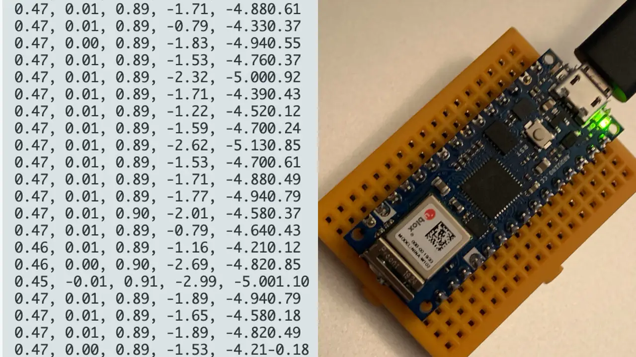
Once the monitor connects, you should see lines of data like this fly by:
0.54, -0.01, 0.85, -1.34, -4.390.24
0.55, -0.01, 0.85, -1.59, -4.760.85
0.55, -0.01, 0.84, -1.83, -5.000.98
0.55, -0.01, 0.84, -1.89, -5.070.92
0.55, -0.02, 0.84, -1.83, -4.880.61
0.55, -0.01, 0.84, -1.65, -4.640.12
To monitor the values live, click the AUTOSCROLL checkbox at the bottom of the monitor.
Test acceleration
- The first three values are the acceleration x, y and z values
- Move the board around in space to see how they change
- The wilder the movements the larger the numbers
Test the gyroscope (orientation)
- The last three values on a line are the gyroscope x, y and z values
- Tilt and rotate the board on each axis to watch the values change
Slow down the readings
You can slow down the readings by adding a one second delay in the loop.
Put this line right after the Serial.println call:
delay(1000);
Why do the numbers change even if the board isn't moving?
The data isn't perfect and is a bit noisy.
You can account for some of the noise by rounding values and testing for ranges in whatever code you decide to write.
Complete Listing
Here is the complete listing of the code used in this article.
#include <Arduino_LSM6DS3.h>

void setup() {
  Serial.begin(9600);
  while (!Serial) {
    ; // wait for serial port to connect. Needed for native USB port only
  }
  if (!IMU.begin()) {
    Serial.println("Failed to initialize IMU!");
    while (true); // halt program
  }
  Serial.println("IMU initialized!");
}

void loop() {
  float aX, aY, aZ;
  float gX, gY, gZ;
  const char * spacer = ", ";

  if (
    IMU.accelerationAvailable()
    && IMU.gyroscopeAvailable()
  ) {
    IMU.readAcceleration(aX, aY, aZ);
    IMU.readGyroscope(gX, gY, gZ);
    Serial.print(aX); Serial.print(spacer);
    Serial.print(aY); Serial.print(spacer);
    Serial.print(aZ); Serial.print(spacer);
    Serial.print(gX); Serial.print(spacer);
    Serial.print(gY); Serial.print(spacer);
    Serial.println(gZ);
    delay(1000);
  }
}
Troubleshooting
Compiler errors
If the code won't compile, look at the compiler error and see if you can spot the problem.
Common problems are:
- missing semi-colon at the end of a statement
- missing closing curly bracket
- variable not spelled correctly
- wrong board or port configuration
If it's still not working, compare your code to the complete listing above
Monitor just shows the fail message
If the monitor shows a fail message then you could be using a different board or the wrong library.
Because of the include this code will only work with a board that has LSM6DS3 IMU.
Monitor not working
When you first fire up the monitor or reload the program, the monitor will temporarily display a message about port unavailble. This is normal until the board connects. If it lasts more than a minute, you may have a port configuration problem. Or the board isn't connected.
Can't connect to the board
If you rebooted your Mac or PC while the 33 was plugged in, you may need to unplug it, then plug it back in. Then it should work.
If you still have trouble, check the cable.
Conclusion
In this article you learned how to do the following:
- Read accleration and gyroscope data from the IMU built into an Arduino Nano 33 IOT board
- Install the LSM6DS3 library to support the IMU on an Arduino
- Initialize the IMU in order to read its data
- Check if IMU data is available
- Assign IMU data to variables
- Monitor changes to the IMU data live
- Slow down the monitored data with a delay statement
Related Articles
- How to Read an Arduino Uno WiFi IMU
- How to Build an Arduino Uno Robot (Free Course)
- Arduino Resource Guide