
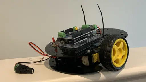
Arduino UNO Robot Hardware Assemble (12 Steps)
In my previous article I showed you how to select hardware for an Arduino UNO Robot. In this article I'll walk you through how to assemble the hardware.
This is part of my free mini-course: How to Build an Arduino UNO Robot. Which I'm making available as a series of blog posts.
Step 1. Mount the motors on the chassis
This article assumes you are using a robot chassis similar to the BONATECH Two Wheels Smart Car Chassis listed in the previous article.
If you are using a different chassis you can probably adapt most of these instructions for it.
You are free to use the motors that came with the chassis. I already had some spare motors that I prefer to use that you can find here:
- Mount the metal brackets to the motors
- Mount the motors to the bottom chassis
- Be sure to mount the motors so that they will both mount with their wires closer to the middle of the robot
- See motor bracket example on Pinterest
Step 2. Mount the Arduino plate to the chassis top
The Arduino UNO WiFi REV2 [ABX00021] that I have comes with a plastic plate for mounting.
- If the board is mounted to the plate, detatch the board from the plate
- You should be able to do this by gently popping it out with a small screw driver
- Be careful not to gauge the board or cut any lines with the screwdriver
- Mount the plate using zip ties
- Mount one zip tie around the middle of the plate
- Mount two zip ties through the screw hole on the flatter end
- You can choose to just leave the zip ties pointing up, giving an antenna, alien or bug like look - or you can just cut them off
- If you cut them off, I recommend filing down any sharp edges
- See zip tie example on Pinterest
Step 3. Mount the top and bottom plates using the standoffs
- Screw the standoffs to the bottom plate - the one with the motors
- When the robot is assembled the motors will be above the bottom plate and inside the chassis
- Line up the top plate with the standoffs
- The mounted Arduino plate should be facing up and on top of the chassis when assembled
- Thread the motor wires up through the base plate
- You can see a picture with the top removed on Pinterest
Step 4. Mount the universal wheel
- Flip the chassis over
- Mount the universal wheel on to the end of the chassis
- The universal wheel will be facing down on the underside of the chassis
- You can see a picture of the universal wheel mounted on the upside down chassis on Pinterest
Step 5. Snap the V2 motor shield on to the Arduino WiFi
When I first got my V2 Motor Shield it was mounted in foam. But that didn't stop the legs from getting bent. Use whatever small tools you have in your toolbox to try to gently straighten them out before proceeding.
- Go slow to avoid damaging the pins on the motor driver
- You should line up the pins and check them before pressing the two parts together
- Line up the ends of each pin on the motor shield with the headers on the Arduino
- Use a small screw driver, or tweezers to line up and straigthen any pins
- Make sure they are in the header and not slipping next to the header
- Slowly press one side of the two boards together
- Then start working on the other side
- Don't be surprised if the long pins don't go all the way in
- What you want is for the pins to be even
- Inspect between the boards
- Make sure all pins went into the header and not inside or outside of it
- Make sure none of the pins are bent
- If something looks wrong, slowly pry the two boards apart, straighten the pins and try again
- See the motor shield snapped into the Arduino on Pinterest
Step 6. Snap the Arduino Uno and motor shield on to the plate
- Snap the Arduino Uno with the motor shield mounted on the the plate
- Be careful not to bend any of the headers on the motor shield
- Try to snap the whole assembly on to the plate by pressing on the sides
- See the Arduino Uno and Motor Shield mounted on to the plate on Pinterest
Step 7. Wire the motors to the motor shield
For this step you will need a small screw driver or an eyeglass screwdriver.
If you are using the motors that came with the chassis, strip the ends if needed.
If you are using the alternative motors like I use, the ends should be all set.
- On the top of the motor shield you will see a header with the following labels:
- M1 - first two pins for the first motor
- GND - common ground
- M2 - last two pins for the second motor
- Wire the red and black wires from the motor closest to M1 to M1
- Wire the red and black wires from the motor closest to M2 to M2
- Depending on how the motors are wired, you may end up needing to reverse the red and black wires later
- This will be figured out later, when the code is uploaded for testing
- You can see how I wired my motors on Pinterest
- I'm using a set of alternative motors with DuPont connectors on them
Step 8. Mount the switch on the chassis
- Put the lock washer on the switch
- From inside the chassis slip the switch up through one of the elongated holes near the back of the chassis
- Put the collar on the switch
- Note that the collar of the switch has a tab
- The tab needs to line up with the groove in the thread or you won't be able to get it on
- Put the hex nut on the switch
- If you have a pair of pliers try to tighten the nut
Step 9. Wire the power switch in series
If there was no switch, you would connect the postive (+) terminal from the female adapter to the postive (+) terminal in the V2 motor shield power header.
So to add a switch you would replace a wire going from the two postive terminals with a switch in series.
Wire the switch between the two positive terminals
For this and the next step, refer to my diagram on Pinterest.
- Strip the end of the red wire coming from the switch
- The switch I use has stranded wire - so be sure to twist it and check for loose strands
- Thread the wire up through the chassis
- On the shield power header:
- Connect the red wire from the switch to the postive (+) power terminal
- Strip the end of the black wire that comes from the switch
- If it is stranded wire, twist it
- On the female power adapter connector:
- Connect the black wire from the switch to the positive (+) terminal
Step 10. Connect the ground wire
- Strip a length of 22 AWG wire
- If you have black wire, use that to indicate ground
- Thread the wire through a hole near the power switch
- Connect the wire to:
- The negative (-) terminal on the V2 motor shield power header
- The negative (-) terminal on the female power adapter connector
Step 11. Put the wheels on
- Put the wheels on
- Be careful not to misalign or put pressure on the plastic motor housing
- If you are having difficulty, make sure the flat edge of the axle is lined up with the flat edge inside the wheel
Step 12. Test the power connection
- Put 6 AA NiMH batteries in the battery holder
- Plug the male connector of the battery holder into the female connector that is wired to the switch and V2 power header
- Strap the battery pack in place with a cable tie to keep it from flying out at high speed
- If the light on the board isn't on, flip the power switch
- If the light still isn't on, disconnect the battery holder and check your connections
Normally I'd have you put the robot on a box where the spinning wheels can't touch the ground. But that isn't a problem until the code is uploaded.
Once you get it assembled, be sure to leave a comment and add a photo to one of the pins on the desertbot.io Arduino board on Pinterest.
In the next article I'll show you how to upload code and run the robot in a motion loop.
Conclusion
In this article you learned how to:
* Mount an Arduino UNO and motor shield to a robot chassis
* Wire motors to a motor shield
* Add a switch
* Wire a battery pack and a switch to the motor shields