
Motor Driver Tutorial (L298N)

In this tutorial I cover how to drive two DC (direct current) motors using an L298N motor driver. Most motorized toys and many robot chassis kits use simple DC motors.
In the first part I will show you how to control the driver without the need for a computer. This will give you a better understanding of how a motor driver works. It should also give you ideas for very simple robot projects.
In the second part I will show you how to quickly wire up the driver to an Arduino. I'll provide a quick demo program so you can see how to run the motors through a predefined sequence.
Step 1. Gather the parts
You can buy the parts for this article by following my affiliate links:
| Part | Amazon |
|---|---|
| L298N Motor Driver | Amazon |
| Gearbox Motors with Wheels | Amazon |
| Jumper Wires | Amazon |
| M2.5 Standoff Assortment | Amazon |
| Mini Breadboard | Amazon |
| Power Supply | Amazon |
| Tool Kit | Amazon |
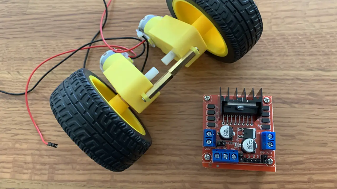
Step 2. Assemble a test rig
This is a quick way of putting together a rig that won't roll away while testing. If you have a 3D printer, clamp, helping hands or some spare parts you can design something a bit more stable.
- Use the standoffs to hold the two motors together
- Make sure that the wires are closer to the middle
- Put a wheel on each motor
- Balance the wheels on a third wheel
- Make sure the wheels aren't touching the supporting wheel
Step 3. Add standoffs to the L298N
This step is optional. But it reduces the chance of shorting if you place the board on metal or spill something on to the work surface.
- From the top of the board, put an M2.5 screw through a hole on the corner of the board
- Hold the screw in place with your finger
- Attach an M2.5 standoff with two flat ends underneath
- Tighten with a screwdriver
- Repeat for the remaining corners
Step 4. Verify the jumpers are set
These instructions are based on the silkscreen of the board that I have. Your silkscreen may or not be different.
This type of board is usually shipped with three jumpers already in place. But in case they are missing or not set, you should verify their placement before proceeding.
The three jumpers are:
- Enable 5V regulator
- ENA (ENABLE A) - Enable Motor A (M1)
- ENB (ENABLE B) - Enable Motor B (M2)
5V Regulator Jumper
The L298N can be powered from 5V to 35V (depending on the specification).
But it is important to note that if you power it with more than 12 volts the onboard 5V voltage regulator will be damaged.
So if you are planning to use more than 12 volts to power the motors, remove the jumper.
In this example I'm not planning to use the regulator. But I'm also not planning to use more than 12 volts. So I just leave the header on.
Enable Motors A and B
There are two ways to drive the two DC motors on an L298N board:
- Full speed with no speed control
- Variable speed using PWM (Pulse Width Modulation)
For a simple robot you can just operate at full speed. To do that you have to put the jumpers on ENA and ENB to pull both PWM pins HIGH. That will enable the motors. It's like sending a PWM signal that is always HIGH - full speed.
If you leave the jumpers off, and do not provide a PWM signal, then the signal will be LOW. That is the equivalent of sending a signal to operate at no speed.
- Verify the ENA and ENB jumpers are set, so the motors will run without the need for a PWM signal
Step 5. Wire the motors to the L298N
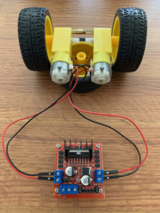
On the board that I have the motor connectors on each side are labeled OUT1 though OUT4.
- Connect the red wire from the first motor (M1) to OUT1 on the L298N board
- Connect the black wire from M1 to OUT2
- Connect the red wire from the second motor (M2) to OUT4
- Connect the black wire from M2 to OUT3
Because the motors are direct current, it doesn't really matter if you wire the red and black wires in reverse. Depending on the board the wiring will determine if both motors operate in the same direction when expected.
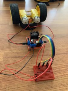
Step 6. Wire the input pins to the breadboard
For this step you will need four (4) different colored female-to-male jumper wires.
- Attach the female-end of a jumper wire to IN1 (INPUT 1) on the L298N board
- Plug the male-end of the jumper into the breadboard on its own row (node)
- Repeat for IN2 through IN4, spacing out the wires on the breadboard in their own rows
Step 7. Connect the 12V power input to the breadboard
- Connect a male-to-male jumper wire to the 12V input on the L298N
- Plug the other end into its own row (node) or rail on the breadboard
Step 8. Connect power
- If you are using a power supply leave it off or unplugged for the now
- If you are using a battery pack that can deliver at least 6V, leave the batteries out for now
- Connect a red wire from your power source to the node or rail on the breadboard wired to the 12V L298N input
- Connect a black wire from your power source to the GND connector on the L298N
- If you are using a variable power supply, preset it to 6V
- Turn on the power supply or put the batteries in
Step 9. Set the direction of the motors
At this point, if your L298N board has an indicator light it should be on and the motors should not be moving.
- Double check that the wheels are not touching the support wheel holding up the test rig
- Plug another red (male-to-male) jumper wire into the 12V row or rail on the breadboard
- Plug the other end of the wire into the row on the breadboard where IN1 is connected - the first motor (M1) should start to spin in one direction
- Unplug the wire from the IN1 breadboard row and the motor should stop
- Now plug the wire into the row for IN2 - the first motor (M1) should now spin in the opposite direction
- Repeat for IN3 and IN4 and note how M2 spins in each direction
In order to run both motors at once, add yet another red wire to the 12V row.
- Plug the first wire into either IN1 or IN2 to control the direction of M1
- Plug the second wire into either IN3 or IN4 to control the direction of M2
What happens if you plug in both inputs for a single motor?
If you pull both inputs for a motor high (by connecting them both to the 12V input) then that will stop the motor, just like if they were both pulled low. The motors will only run if one input is high, setting the direction.
Now that you understand the basics of how the L298N works you could build a simple robot using long cables and push buttons wired to IN1 through IN4. If you use push-on/push-off buttons you could create a game where you chase the robot around and tap the buttons to get it to change direction.
Testing with an Arduino Nano
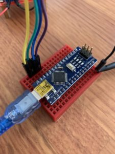
Below is a simple program to run the motors through a sequence using an Arduino Nano. You should be able to easily adapt the wiring to most other Arduino devices.
- Turn off the power supply or remove the batteries from your power pack
- Remove all the wires from the breadboard
- Plug an Arduino Nano into the breadboard
- Wire IN1 from the L298N to D12 on the Arduino Nano
- Wire IN2 from the L298N to D11 on the Arduino Nano
- Wire IN3 from the L298N to D10 on the Arduino Nano
- Wire IN4 from the L298N to D9 on the Arduino Nano
- Wire a jumper from GND (ground) to GND on the Arduino Nano
- Plug the USB cable from the Arduino Nano into your computer
- Using the Arduino IDE, push the code below to the Nano
- Reconnect your power source
- Verify that the motors run through a sequence
Arduino Full Speed Demo
#define in1 12
#define in2 11
#define in3 10
#define in4 9

int counter = 1;

void setup() {
  pinMode(in1, OUTPUT);
  pinMode(in2, OUTPUT);
  pinMode(in3, OUTPUT);
  pinMode(in4, OUTPUT);
  // Stop all motors
  digitalWrite(in1, LOW);
  digitalWrite(in2, LOW);
  digitalWrite(in3, LOW);
  digitalWrite(in4, LOW);
}

void loop() {
  int currentPin = in1;
  if(counter > 4) {
    counter = 1;
  }
  switch(counter) {
    case 1:
      currentPin = in1;
      break;
    case 2:
      currentPin = in2;
      break;
    case 3:
      currentPin = in3;
      break;
    case 4:
      currentPin = in4;
      break;
    default:
      break;
  }
  digitalWrite(currentPin, HIGH);
  delay(3000);
  digitalWrite(currentPin, LOW);
  counter++;
}
Conclusion
In this tutorial I showed you how to setup an L298N motor driver to drive two DC (direct current) motors. First I showed you how to control the motors without a computer. Then I gave you a quick demo of how to control the motors using an Arduino Nano.
Now you have enough information to build a simple wheel-based robot. Or you could use the information to either modify motor-based toys or design some new motorized project.
An exercise for the reader is to figure out how to wire the PWM pins to an Arduino to control the speed of each motor. You could either do it programmatically or read a potentiometer to set the speed.
Related Articles
- How to Build an Arduino Uno Robot (Free Course)
- PCA9685 Servo Driver with Seeeduino Nano (Arduino Compatible)
- Arduino Resource Guide
References
- Arduino Nano Manual with Pin Diagram (source)